Dune 3D for woodworking
Spring is here and it's the first time we have our own garden to enjoy it! It's not very large (as you'll see later on) but we're set on making the most out of it.
the goal
You can skip this section if you only care about the CAD process
We want to build a raised bed planter for our garden. When we moved here, the garden was mostly decorative and most of the space was taken up by bushes and small trees.
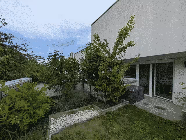
In September of last year, we moved some of the trees to the left side (an apple and a pear tree) and rehomed the rest of the trees to friends and family.
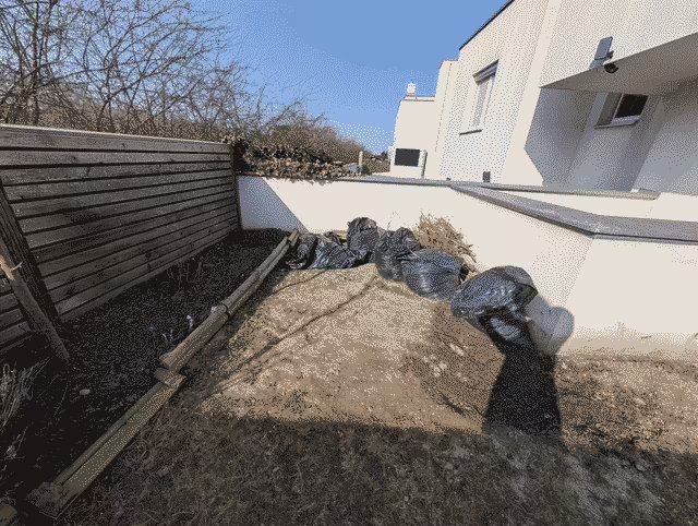
We're now left with a big empty patch of dirt which will become the location of our new vegetable garden.
Our plan is to move the storage chest to the right hand side of this nook and build an L-shaped raised bed planter against the back wall with a lower section extending to the front. The reasoning behind the lower section is to provide a space with a bit more shade in the afternoon and evening.
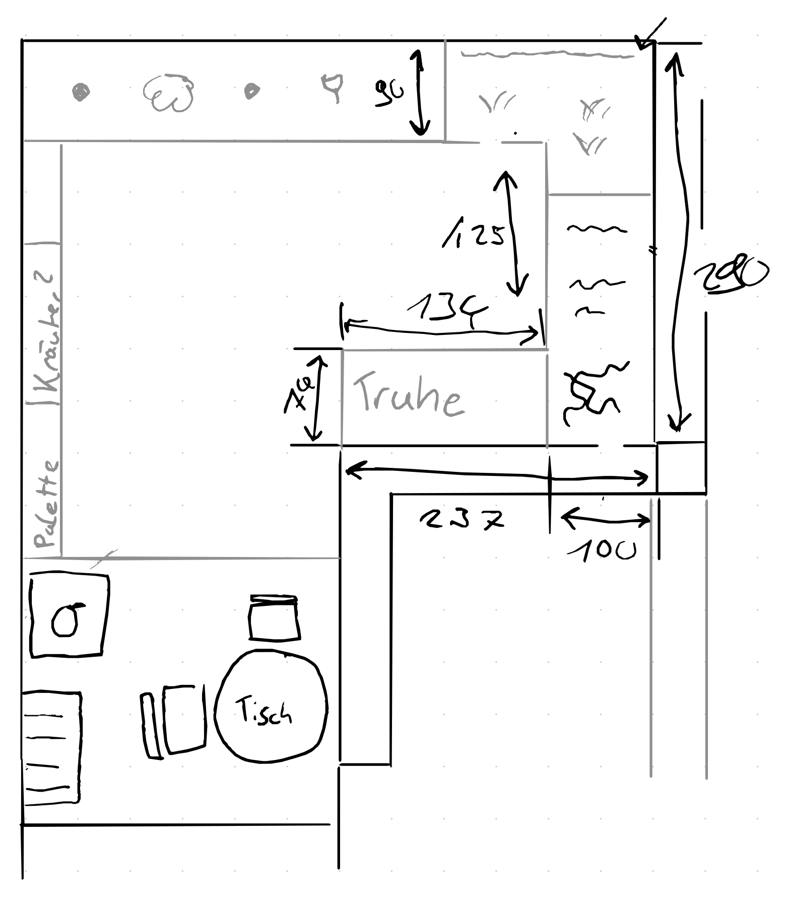
We sketched out this top-down view while on a coffee date last Tuesday without worrying about measurements for now. This turned out to be a good idea as it allowed us to quickly iterate on ideas without worrying about scale and accuracy. The downside of this approach was worrying about if our final design actually fits the space.
On Thursday, I went outside with a tape measure and added measurements to the plan. Luck was on our side and our rough draft seemed possible!
We now had the concept of a plan but while we could put together something based on this alone, we needed exact measurements to buy the correct lengths of wood.
I started out sketching this with pen and paper as well but my sketches were hardly legible and I didn't fully trust my math so I started looking into CAD software to plan this with the help of ✨computers✨.
why Dune 3D?
A search for "woodworking cad software" brings up many lists and tools. The most popular choices seem to be SketchUp, Fusion360 and Solidworks. While I presume most of these are good tools for the job, every one of these is unusable to me since they don't run on Linux. This left me with three choices: OpenSCAD, FreeCAD and Dune 3D.
I quickly ruled out FreeCAD as my previous tries were all disastrous. OpenSCAD is really great and I use it frequently to design 3D printed parts but for this use case, I dreaded the complex math I'd have to write for this to work well. Also, I worried I'd care more about writing clean and modularized OpenSCAD code and never get this done so it was off the table as well.
My colleague Nadia shared Dune 3D in one of our internal hobby channels some time ago and I was intrigued from the start. It's easy to use, supports 2D and 3D sketches and runs well on Linux - what's not to love? So far, I only ever used it to design small, single-body parts so I knew I'd at least learn something new!
starting to sketch
As a base for our plans, I researched some common designs and ended up with this DIY guide from a local hardware store. It has all the important details, feels solid and looks good.
One quality of life improvement I wanted to make was to add a topper so we can lean on it and place stuff on it.
As the available area is constrained in all directions, I started building the planter from the top down. The first sketch is the outline of the available area:
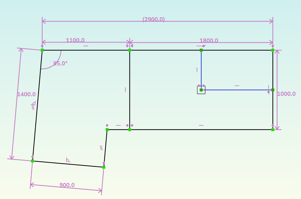
By doing this sketch first, I can always come back and change around lengths & proportions and everything referencing this will change automatically.
working with planks
Now it's time to draw the first actual plank. The topper I had in mind was a ring of planks, joined with 45° angles like this: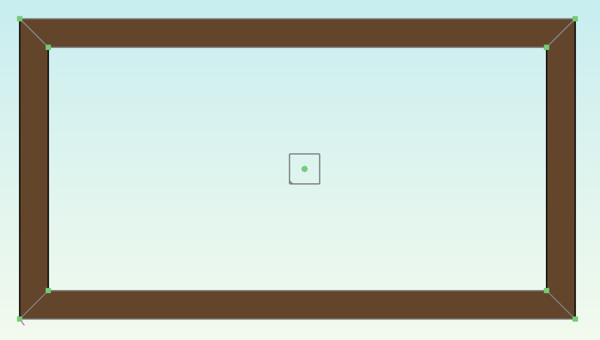
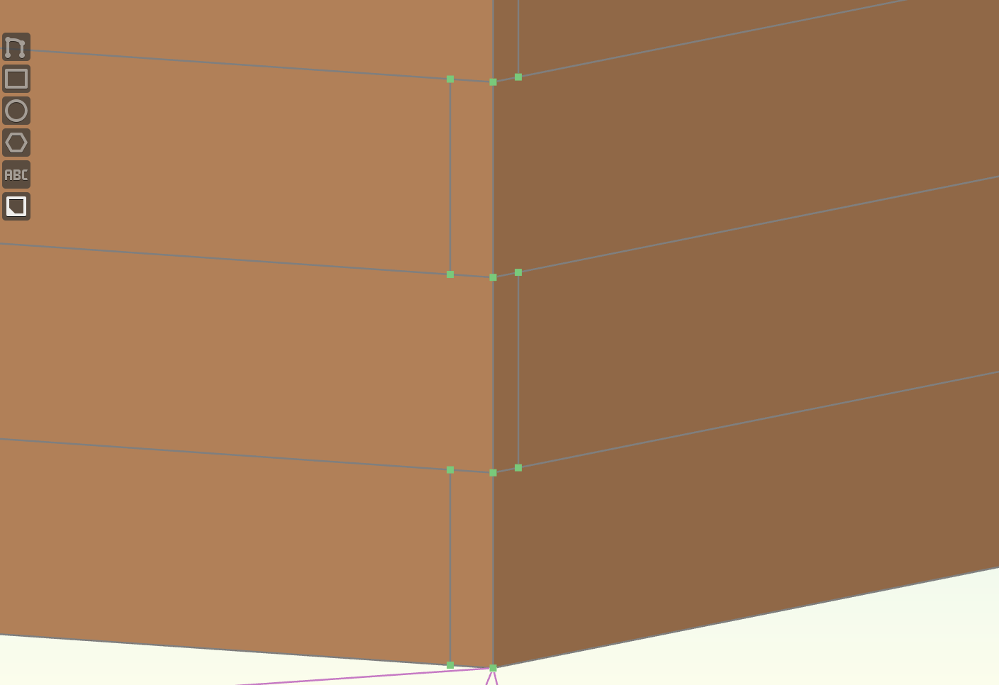
Looking at this, you might be tempted to draw this as a single sketch and then simply extrude it. This is what I tried in my first attempt as well but quickly found out that this does not work as the extrude group fails with a mysterious no faces found error.
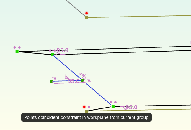
This occurs as soon as two faces share a point which left me confused at first. Only after asking about this in the projects matrix room did I realize that technically, faces sharing a single point are overlapping so the constraint solver doesn't know if they should extract to a single object or not.
For 3D Printing or subtractive manufacturing, this is not an issue as you're mostly working with a single work piece anyways so you can use boolean logic to join bodies and groups. But for woodworking, I want to keep the planks separated so I can measure the dimensions calculated by the solver.
Luckily, working around this is not complicated. As long as you create separate sketches, everything works out fine. You can reference points and lines in earlier sketches so you don't have to worry about getting constraints wrong.
This technique is what I used to build the topper:
the rest of the owl
Once I had this down, I had to do the same thing for the walls. Sketching them to be perfectly in the middle of the topper was a breeze but why keep it simple if we can make it ✨fancy✨?
To complicate our first large-scale woodworking project, we wanted to have the corners overlap in an alternating pattern like this:
My approach modeling this, was to construct the body in layers. For the first "ring", the process was the same as with the topper: Create two sketches (one for the vertical and one for the horizontal planks) and extrude them to the same height.
Then, I created another set of two sketches on a workplane on top of the extrusion, this time with the corners overlapping in the opposite way.
I could then use the Linear Array group to repeat this parametrically. This group can work on a range of sources which makes it possible to select both the horizontal and the vertical planks. The trick to placing them at the right location is selecting the First Copy offset mode. Reduce the copies to 1 to make sure you're working with the correct one and constrain the anchor point to coincide with the bottom corner of the alternated plank.
You'll then have to do the same thing with the other set of planks and now you can freely choose the amount of planks just by changing the number of copies!
taking the "L"
For the extension off to the side, it was just a matter of doing the same thing with less copies. One interesting thing to point out is that you can create constraints across sketches, even if they are not on the same elevation (as long as they are oriented in the same way).
This was very useful here as it allowed me to repeat the same top-down modeling approach to keep in the bounds of the original sketch.
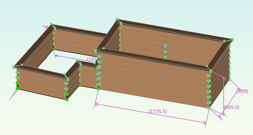
I continued sketching, extruding and linear-arraying (?) until I was left with the final, fully constrained model of our planter:
building the darn thing
The only thing left now is to actually build the darn thing. You might also notice that this model is missing corner posts and braces to prevent the walls from bulging out but I didn't think I'd need to model them as well as we're just going to buy them in roughly the correct height and cut them to correct size once everything is screwed together.
I'd love to tell you how well everything went when building this in the real world but at the time of writing, there are still ~2 weeks left until we have the time to build this so this will be the topic for a future post. I'll also link it here once finished (as long as I remember 😅).
If you'd like to learn more, drop me a message on matrix (which I've finally
gotten around to host again 😬) or send a mail to hello@<this-domain>.